Sfd And Bmd Examples / Bending Moment Diagram2 Examples Assignment Help. Ansys is a software tool used by engineers to perform variety of analysis on mechanical parts and systems. Learn vocabulary, terms and more with flashcards, games and other study tools. Axial force diagrams come additionally for column design. Contribute to virtuallypassedsmartsparrow/sfd_bmd_q1 development by creating an account on github. #sfd_bmd #sfd_bmd_continuous_beamhello friends,this video tutorial is on request of many people who wanted the sfd and bmd for continuous beam with udl and.
Example (2)draw the shear and bending moment diagrams for the beam and loading shown. Understanding these forces conceptually is the key to understanding their use in design and field. Construct the sfd and bmd for 10 m span simply supported beam subjected to a system of loads as shown in figure 4.32. 34 example problem example problem 3 3. What is sfd and bmd, types of supports and beams.
SFD & BMD #3:How to make SFD & BMD (in Hindi) - Unacademy from edge.uacdn.net Below are the beam formulas and their respective sfd's and bmd's. 63 sfd bmd 30kn 10kn 50kn parabola x = 1.5 m parabola 20knm 10knm point of contra flexure bmd cubic parabola 20knm. Draw sfd and bmd for the cantilever beam of 3 m long which carries a uniformly distributed load of 2 kn/m over a length of 2 m from the free end. Learn vocabulary, terms and more with flashcards, games and other study tools. Sfd and bmd for a simple beam with a concentrated load. Determine the absolute maximum bending moment and shear forces and mark them on sfd and bmd. Get the unknown sf and bm. Draw sfd and bmd for the single side overhanging beam subjected to loading as shown below.
Draw shear force and bending moment diagrams sfd and bmd for a simply supported beam subjected to three.
(a) determine reactions by considering the equilibrium of the entire beam. Learn vocabulary, terms and more with flashcards, games and other study tools. Draw sfd and bmd for the single side overhanging beam subjected to loading as shown below. A simply supported beam is the most simple arrangement of the structure. ◀ ← video lecture 16 of 41 → ▶. Draw fbd and find out the. Page 8 of 13handout ansys examples. Planar rigid body statics example 1 6: What will be the variation in bmd for the diagram? To draw this diagram , we have to find out the. Determine the maximum normal stress due to. You can also use following useful calculators. Shear force and bending moment diagrams sfd & bmd.
A simply supported beam cannot have any translational displacements at. You can also use following useful calculators. Draw sfd and bmd for the single side overhanging beam subjected to loading as shown below. 63 sfd bmd 30kn 10kn 50kn parabola x = 1.5 m parabola 20knm 10knm point of contra flexure bmd cubic parabola 20knm. Draw shear force and bending moment diagrams sfd and bmd for a simply supported beam subjected to three.
SFD & BMD from image.slidesharecdn.com Problem 2 based on sfd and bmd part 1 video lecture from shear force & bending moment in beams chapter of strength of materials subject for all this video explains typical example on how to draw shear force & bending moment diagram ( sfd & bmd) in case of simply supported beam. ◀ ← video lecture 16 of 41 → ▶. 2)for uniformly distributed load load(udl) the degree of curve is 1st(linear) in sfd and 2nd(parabola) in bending moment diagram(bmd). Planar rigid body statics example 1 5: Sfd stands for shear force diagram. #sfd_bmd #sfd_bmd_continuous_beamhello friends,this video tutorial is on request of many people who wanted the sfd and bmd for continuous beam with udl and. A simply supported beam is the most simple arrangement of the structure. Draw the shear force and bending moment diagrams for the beam shown in fig.
Sfd stands for shear force diagram.
63 sfd bmd 30kn 10kn 50kn parabola x = 1.5 m parabola 20knm 10knm point of contra flexure bmd cubic parabola 20knm. .force and bending moment diagram when you will see condition like uniform distributed load then the problem becomes little difficult to solve properly but the concept i have used to solve this problem that is just really awesome, because i knew how students face problems to solve sfd and bmd problems. (a) determine reactions by considering the equilibrium of the entire beam. 0 ratings0% found this document useful (0 votes). Axial force diagrams come additionally for column design. Also locate points of contra flexure if any. What will be the variation in bmd for the diagram? Planar rigid body statics example 1 6: Page 8 of 13handout ansys examples. The beam is supported at each end, and the load is distributed along its length. A simply supported beam is the most simple arrangement of the structure. I have explained how to find them. All 3)for uniformly varying load load(uvl).
Example problem example problem 3 3. ◀ ← video lecture 16 of 41 → ▶. Types of load, equilibrium equation and reaction calculation. In this video i have described what is sfd and bmd of cantilever beam which is carrying a point load at its free end. 34 example problem example problem 3 3.
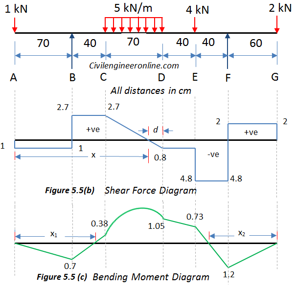
Solving for SFD and BMD of Overhanging beam: Prob 5.5 - Civil Engineer Online from civilengineeronline.com All 3)for uniformly varying load load(uvl). Problem 2 based on sfd and bmd part 1 video lecture from shear force & bending moment in beams chapter of strength of materials subject for all this video explains typical example on how to draw shear force & bending moment diagram ( sfd & bmd) in case of simply supported beam. Use equilibrium conditions at all sections to. Understanding these forces conceptually is the key to understanding their use in design and field. Planar rigid body statics example 1 5: Below are the beam formulas and their respective sfd's and bmd's. 2)for uniformly distributed load load(udl) the degree of curve is 1st(linear) in sfd and 2nd(parabola) in bending moment diagram(bmd). Draw fbd and find out the.
The beam is supported at each end, and the load is distributed along its length.
It can be made from the loading diagram of the cantilever beam. What will be the variation in bmd for the diagram? Determine the maximum normal stress due to. ◀ ← video lecture 16 of 41 → ▶. 2)for uniformly distributed load load(udl) the degree of curve is 1st(linear) in sfd and 2nd(parabola) in bending moment diagram(bmd). Shear force and bending moment diagrams sfd & bmd. Draw the shear force and bending moment diagrams for the beam shown in fig. Learn vocabulary, terms and more with flashcards, games and other study tools. Also locate points of contra flexure if any. Planar rigid body statics example 1 6: Determine the absolute maximum bending moment and shear forces and mark them on sfd and bmd. Problem 10 based on sfd and bmd video lecture from shear force & bending moment in beams chapter of strength of materials subject for all engineering student. Draw sfd and bmd for the cantilever beam of 3 m long which carries a uniformly distributed load of 2 kn/m over a length of 2 m from the free end.
I have explained how to find them bmd sfd. Draw sfd and bmd for the single side overhanging beam subjected to loading as shown below.
Share :
Post a Comment
for "Sfd And Bmd Examples / Bending Moment Diagram2 Examples Assignment Help"


Post a Comment for "Sfd And Bmd Examples / Bending Moment Diagram2 Examples Assignment Help"